

From Concept to Creation: 3D Printing Chronicles
- Arash Khazaie

- Feb 19, 2024
- 4 min read
Updated: Mar 22, 2024
In the intricate landscape of product development, each step offers valuable insights, driving us closer to the pinnacle of functionality and user satisfaction. Our recent foray into 3D printing has provided us with a wealth of information, illuminating both triumphs and areas ripe for improvement in our mechanical design. Join us as we dissect the outcomes of our 3D print results, charting a course toward enhanced performance and seamless user interaction.
The Ring
The image below showcases all the design iterations that have undergone 3D printing thus far. The purpose of the ring is to securely hold the mini thumbstick onto the pointer finger, minimizing sliding.

The 3D print of the ring component turned out flawless, requiring no alterations to the original model. Surprisingly, it seems that the set screw may not be necessary after all, but we'll keep it as a precautionary measure.
The Wrist Mount
The image below displays all the design iterations that have been 3D printed thus far. The purpose of the wrist mount is to securely hold the peltier using the rails and tighten around the wrist using velcro.

Upon reviewing the print results for the Peltier mount, we noted that the supports used during printing significantly marred the surface finish, necessitating extensive sanding. To mitigate this issue in future iterations, we've decided to forgo supports altogether.
Additionally, if we manage to procure a heat sink smaller than 27.5x27.5mm, we'll modify the model accordingly. However, integrating the heat sink will require adhesive thermal paste or pads, as securing it directly to the mount would be impractical.
While removing the ribs for improved cooling is tempting, it poses a safety hazard, as users could accidentally touch the hot surface. Instead, the width of the ribs were reduced from 2mm to 1.5mm to increase the surface area exposed.
Considering a switch to PETG filament for its higher glass transition temperature compared to PLA (60°C) is a proactive measure, though it's unlikely we'll reach such temperatures.We've also implemented minor tweaks to enhance printing quality and ensure the Peltier sits flush with the mount's bottom surface.
Update:
In a recent development, we decided to refine the design of the wrist mount by transitioning the shape of the cutout from triangles to squares. This strategic adjustment aimed to maximize the exposed area, thereby enhancing functionality. Following the implementation of this modification, we were delighted to find that our expectations were not only met but exceeded. While each triangle previously offered an area of 136mm^2, the square configuration now provides a generous 154mm^2 of exposed surface area.
Additionally, we've identified small 1x1 cm heat sinks available at MESS that can be inserted into each cavity to further enhance cooling performance. These heat sinks promise to significantly improve the cooling period, ensuring optimal operation of the device. The images below showcase the latest revisions in descending order, offering a comprehensive view of our progress in refining the wrist mount design.


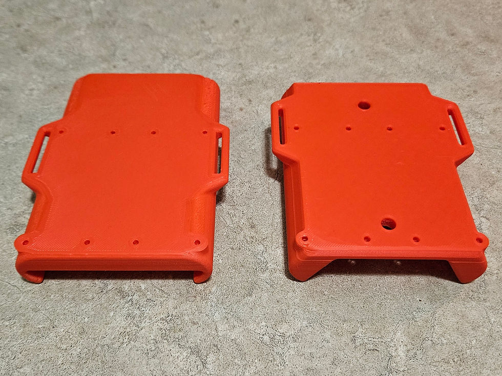
The Forearm Mount
The latest iteration of the battery mount resolves the issue of the battery sliding when picked up from a table, marking a significant improvement over previous versions. However, we observed that the friction decreases once the mount is tightened around the arm, causing slight shifting due to the smooth surface. To address this, we plan to transition to an Interference Fit method, albeit at the cost of making battery insertion more challenging.
Increasing the lead-in chamfer size and angle should alleviate this difficulty. While set screws offer a solution, they necessitate the use of an Allen key for battery replacement. It's worth noting that users can charge the battery without removing the mount, mitigating the inconvenience of set screws. Over time, the friction between the battery and mount will diminish, emphasizing the need for alternative tightening methods like set screws.
Wearing the device with long sleeves proves more comfortable, prompting consideration for a wristband or forearm support to distribute force and minimize discomfort. Additionally, eliminating one mounting hole for each perfboard should suffice, slightly reducing the model's size.
Update:
We successfully resolved the sliding issue has been completely resolved by enhancing the fit between the battery and the mount. This was achieved by strategically adding three layers of Scotch tape to each side, effectively increasing the thickness and resulting in greater friction. As a result, the battery remains securely in place and no longer falls out unless intentionally pulled. Consequently, the previously planned 2xM5 heat insert holes, intended for set screws to tighten the battery, are no longer necessary.
Moreover, significant strides have been made in weight reduction efforts. By strategically reducing wall thickness where unnecessary, we've managed to shed a considerable amount of weight from the design. For reference, while the latest printed revision weighed 49.64g, the updated version now weighs a lean 39.98g.
In addition to these improvements, we identified a more suitable 7x9 cm perfboard at MESS for our project's needs. Consequently, the mounting holes originally designed for an 8xM2 heat insert had to be modified to accommodate 4xM3 heat inserts. This adjustment ensures compatibility with the new perfboard and aligns with our project's specifications. The images below showcase the latest revisions in descending order, offering a comprehensive view of our progress in refining the forearm mount design.


Conclusion
These insights from our 3D print results guide our ongoing refinement process, ensuring optimal performance and user experience.


